|
Touch Activated Keyboard SequencerParts for Kit
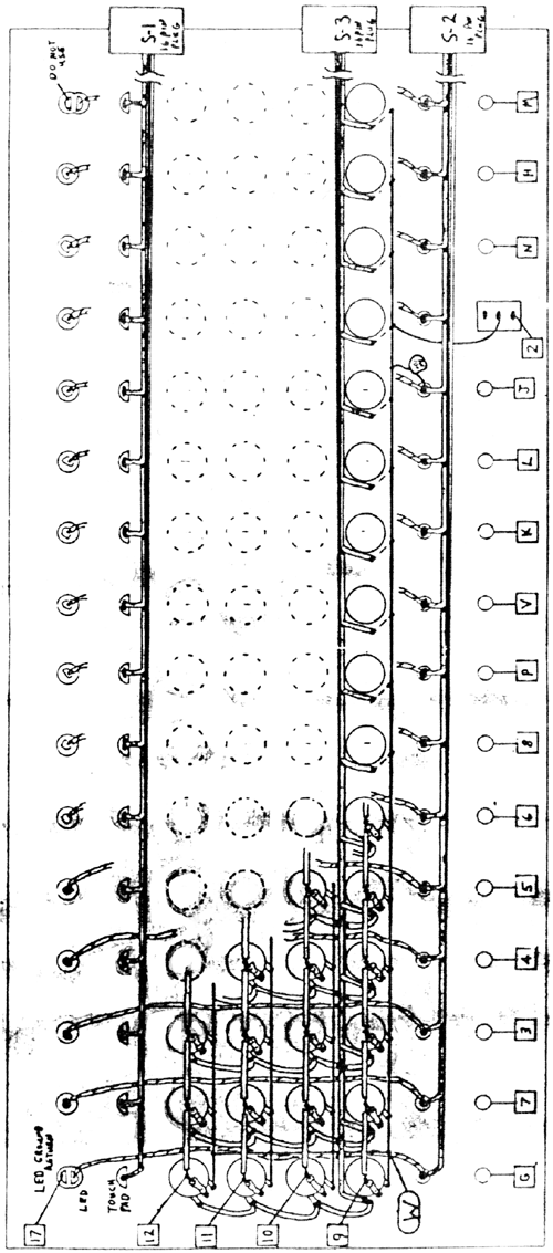
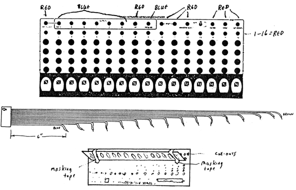
The wiring of the TKB is made easier with the use of 16-pin 'header' plugs that fit into IC sockets on the KBD PC board. The main wiring consists of connecting the various ground busses and signal busses to form a matrix with the 64 potentiometers. For the neatest assembly, the following steps should be done in order. Care should be taken throughout this wiring to the potentiometers since this is the part of the assembly where errors are most likely to occur. Short circuits, poorly soldered joints, burned insulation, and all of the little gremlins that can creep into your assembly of this unit must be avoided... Once this portion of the wiring is completed, there is very little left to be done. 1. Apply graphics, pots, jacks, and switches as described in the Kit Manual. 2. Install the 4 horizontal ground busses using bare wire along each row of potentiometers. Install the vertical buss wire to connect the four horizontal ground busses. This connection will later be connected to pad W on the KBD PC board. 3. Install the insulated wire jumpers linking up the four potentiometers in each column as shown.. Do not solder the bottom connection yet, since the ribbon wire will be connected to this lug later. 4. Install the 1M resistors as shown on the center lugs of each potentiometer. These resistors should lay at about a 45 degree angle across the top of the potentiometers. The insulated parts of the resistor body may lean on the metal case of the potentiometer, but the leads should be trimmed quite short where they connect to the lugs of the potentiometers. The top lead from each resistor should be able to reach over to the next resistor, and the end can be formed with a small hook to be crimped around the top lead of the next resistor and soldered. Teflon tubing should be used on these long leads. 5. Cut the ribbon cable so that each wire is exactly 1" shorter than the adjacent wire, as shown in the diagram above. This can be done by peeling the blue wire back to 6" from the plug, then peeling the green wire to 7" from the plug, then the yellow wire to 8" and so on. The longest wire will be the brown wire. The length of the brown wire should be about 22". Usually the ribbon cables packed with the TKB kits ore much longer. Strip away about l/8 of insulation and tin the leads for ease of soldering in the following steps. 6. Position the TOUCH assembly on the panel face where it will later be installed, but do not peel away the backing from the double stick tape. Using masking tape, tape the TOUCH assembly so that it is in an open position as shown in the diagram. Now the wires from the red Pulse Output Jacks can be installed, feeding under the potentiometer wiring matrix, through the cut-outs on the panel, to the LED pads on the underside of the TOUCH Panel. These sixteen pads are in the center of the underneath of the TOUCH Panel. The end pads are split into two sections. The wire to pad 17 will be soldered onto one section as seen from the diagram. 7. Connect the three ribbon cables to the appropriate places. Note that one is wired along the row of pulse output jacks, one is wired along the bottom row of potentiometers (with the wires which were not soldered in step 3). The ribbon cable which goes to the TOUCH assembly goes through the cut-outs in the panel to the 16 connectors along the top edge of the TOUCH Panel. There should be the absolute minimum of bare wire extending up from the solder connection to prevent shorts when the TOUCH Panel is installed onto the metal panel. The wires from the ribbon cable that are soldered to the small pads going to the large touch pads should not be inserted into the holes. These leads should be cut very short, and soldered flat onto the pad, using a minimum of solder. It won't affect the operation if wires or solder extend through these holes, but for best appearance this should be. 8. Install the metal stand-offs onto the panel as detailed in the Kit Manual. Two will be installed in the left-most holes, and two will be installed in the two special holes which have been drilled into this panel. The stand-offs will hold the KBD PC board through the four holes in each corner. No rails are needed in this panel. 9. Stick the TOUCH Panel onto the panel with the two sided tape. Make sure to align the solder pads on the underside with the cut-outs in the panel. Check that all connecting wires go directly through the cut-outs, and are not crimped between the TOUCH assembly and the Panel. Also visually inspect each connection after the TOUCH assembly is installed that no bare wires are touching the Panel. 10. Wire the PC board as described in the Kit Manual. 11. Apply the power supply cables as described in the Kit Manual. 12. Attach the PC board to the stand-offs, and connect the 16-pin "header" plugs to the proper sockets. Each socket is labelled on the PC board. The arrows on the PC board should point directly at the tip of the arrow on the 16-pin plugs. --> <-- Adjustments for this module are very important for proper operation. There are two trimmers on the PC board. The one labelled SENS should be adjusted first. It should be adjusted as received from the factory, but it is possible that it might need to be re-adjusted after assembly. This trimmer when turned all the way counter-clockwise will cause all the LED's on the Touch Panel to be on simultaneously. This adjustment should be turned clockwise until only one LED is lit. Next apply a fast pulse to the CLOCK input and, while touching a pad with the KEYS switch on. adjust the SENS trimmer so that the adjacent LED's do not flicker; i.e. only the LED for the stage being touched is on. The second trimmer labelled PRES is used to adjust the pressure action of the touch pads. This can be adjusted to user preference. It should not be turned all the way up or down, since some erratic operations have been traced to extreme settings of this adjustment. What to do if you have problems: 1. Check your wiring against the wiring diagram. The most common problem is omitting a wire. Make certain that the ground matrix is connected to pad W and that all four of these horizontal bare busses are connected together as shown where the W pad is drawn. 2. Make sure that the center pole of the switch is connected to the ground buss as shown. 3. Double check all the 16-pin header connections. It won't hurt if they are plugged into the wrong place, or if they are in backwards, but you'll get some very strange things happenings, such as wrong LED' s lighting, or incorrect voltages at outputs. 4. Make sure that all IC's are firmly in their sockets. It is possible for them to be jarred loose in transit. 5. Check for shorts on the potentiometer wiring matrix or the TOUCH assembly wires. 6. Check for shorts against the Chassis Box when the Panel is installed. Clearance is minimal for potentiometer lugs on the left side, so if stage 1 gives you problems, carefully inspect the way the TKB and panel mount into the BOX. 7. Go through the adjustment procedures as described above. Here are a few preliminary checks to ensure that your TKB is working properly:
|

|
